BIMQuality Revit Addin
⭐ BIMQuality – The Ultimate Productivity Add-in for Revit
Work Faster. Avoid Repetitive Tasks. Build Projects with Confidence.
BIMQuality is a collection of smart, time-saving tools designed for everyday Revit users, engineers, architects, and BIM coordinators.
Instead of doing repetitive tasks manually, BIMQuality automates them with one click — saving hours of work on every project.
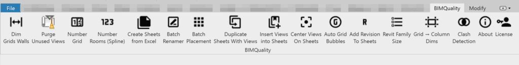
The add-in installs as a full ribbon tab inside Revit, making all tools easy to access and simple to use.
🚀 What BIMQuality Does for You
Whether you’re numbering rooms, cleaning unused views, creating sheets, placing views, or detecting clashes —
BIMQuality does the boring work automatically, so you can focus on design instead of manual workflows.
Below is a user-friendly explanation of each feature.
🧰 TOOLS INCLUDED (Simple Explanation for Normal Users)


Learn Center
Dimension Grids & Walls – Quick Guide
🔹 What this tool does
The Dimension Grids & Walls tool automatically creates a clean dimension chain between multiple Grids and/or Walls in your active view.
Instead of placing dimensions manually one by one, the tool analyzes the selected elements, checks if they are parallel, finds the correct alignment direction, and creates a full dimension line with a single click.
It helps you:
Quickly dimension grids and walls in plans or sections
Ensure perfect alignment and spacing
Avoid manual mistakes or skipped elements
Speed up documentation significantly
🟦 How to Use the Tool
1️⃣ Select Grids and/or Walls
When you run the command, Revit will ask you to select elements:
“Select Grids and/or Walls to dimension.”
✔ You can select any combination
✔ Must be straight
✔ Must be parallel to each other
2️⃣ The Tool Validates Your Selection
The tool checks:
Are all grids/walls straight (linear)?
Are they parallel in the current view?
Are there at least two valid references?
If anything is invalid, a message will appear.
3️⃣ The Tool Determines the Dimension Position
It automatically calculates:
The top-most point of your elements
A safe offset above them (300 mm)
A long dimension line spanning the full set
No manual alignment needed.
4️⃣ Dimensions Are Created Automatically
A single continuous dimension line is placed between all selected grids and walls—using Wall Centerlines if enabled in your Dimension Type.
5️⃣ Done
A final message confirms that the dimension chain has been created.
Purge Unused Views – Quick Guide
🔹 What this tool does
The Purge Unused Views tool scans your Revit project and finds all views that are not placed on any sheet and are safe to delete.
It groups these views by type (Floor Plans, Sections, 3D Views, Schedules, etc.) and lets you select exactly what you want to remove.
It helps you:
Clean your project from unused views
Reduce file size and improve performance
Remove duplicated / old / test views
Keep your project browser organized
Avoid deleting anything important (active view, template, or placed views are protected)
🟦 How to Use the Tool
1️⃣ The tool scans your project
It automatically detects:
Views placed on sheets
Schedules placed on sheets
View templates (ignored)
Active view (locked from deletion)
Only safe, unused views are shown.
2️⃣ Choose what you want to delete
A window appears showing:
View groups (Floor Plans, Sections, 3D, Drafting, Schedules…)
A checkbox for each view
“Select All” for each group
“Select All” for the entire project
Active view is displayed but cannot be selected.
3️⃣ Confirm deletion
Click Delete Views and the tool will safely remove the selected views.
Views that cannot be deleted (due to dependencies) will be listed in a small report.
4️⃣ Done
A summary displays:
How many views were deleted
Any failures (rare)
Number Grids – Quick Guide
🔹 What this tool does
The Number Grids tool automatically renames your Grid lines in Revit using a prefix and a starting value (Seed).
Instead of renaming grids one by one, the tool sorts the grids according to a direction you choose and applies a clean sequential numbering or lettering system.
It helps you:
Quickly renumber grids in plans
Maintain consistent naming (1, 2, 3… / A, B, C… / 01, 02…)
Control direction and order of numbering
Avoid mistakes and duplicated grid names
🟦 How to Use the Tool
1️⃣ Select the Grids
You can:
Pre-select multiple grids, or
Click them manually when prompted
Only Grid elements can be selected.
2️⃣ Pick Numbering Direction
The tool asks you to click two points:
Start point → where numbering begins
End point → where numbering moves toward
This defines the sorting direction.
3️⃣ Enter Prefix + Seed
A small dialog appears:
Prefix → optional text before the grid name
Seed → starting value
Examples:
1,01,A,aa
The tool automatically handles:
Numeric and alphabetic sequences
Upper/lowercase
Zero-padding (001 → 002 → 003)
4️⃣ Grids Are Renamed Automatically
All selected grids are renamed in the chosen order.
5️⃣ View the Summary
A quick report shows:
How many grids were successfully renamed
Any items that failed (rare)
Auto Number Rooms by Spline – Quick Guide
🔹 What this tool does
The Auto Number Rooms by Spline tool automatically renumbers rooms based on a curve/spline path that you pick inside your project.
Instead of manually renumbering rooms one by one, the tool:
Lets you define a numbering path using any curve (Spline / Line / Arc)
Lets you pick the rooms you want to number
Sorts them according to their projection onto the spline
Generates numbering sequences (numeric or alphabetical)
Applies prefix, padding, and reverse direction if needed
It helps you:
Number rooms in the exact order of corridor flow
Maintain clean and consistent room numbering
Save hours of manual work
Avoid duplicate or random numbering
🟦 How to Use the Tool
1️⃣ Pick the Spline / Curve
Click Select Spline in the dialog.
Revit will ask you to pick a curve element (Spline, Line, or Arc) that represents your numbering direction.
This curve defines:
The order of rooms
The direction of numbering
2️⃣ Select the Rooms
Click Select Rooms and pick any number of rooms in the model.
The tool only accepts rooms with a valid location point.
The dialog will show how many rooms you have selected.
3️⃣ Set Numbering Options
In the dialog, you can enter:
Prefix
Optional text before the number
Example: L1-, R-, FL-
Seed
The starting value, supports:
Numeric:
1,01,001,10Alphabetic:
A,AA,a,bb
The tool auto-detects numeric vs alphabetic sequences.
Reverse
Enable this option if your numbering should go in the opposite direction of the spline.
4️⃣ Run the Numbering
When you click OK:
Each room is projected onto the spline
Rooms are sorted along the curve
A numbering token is generated for each room
The tool renames room numbers inside a single transaction
If anything is missing (no spline, no rooms, no seed), the dialog will prompt you to fix it.
5️⃣ Summary Report
When complete, a report shows:
Renamed: number of rooms successfully updated
Failed: rooms that could not be renamed (e.g., duplicate number conflicts)
Create Sheets From Excel – Quick Guide
🔹 What this tool does
The Create Sheets From Excel tool allows you to automatically create multiple Revit sheets using data from an Excel file.
Instead of creating sheets manually one by one, the tool reads sheet numbers and sheet names directly from Excel and generates all sheets instantly.
It helps you:
Create large sets of sheets in seconds
Eliminate manual entry and typing mistakes
Keep sheet numbering and names consistent with your Excel schedule
Use any title block family in your project
Avoid duplicate sheet numbers automatically
🟦 How to Use the Tool
1️⃣ Select the Excel File
Click Browse, choose your Excel sheet (XLS or XLSX), and load it into the dialog.
2️⃣ Choose the Title Block
Select the title block type that will be used for all newly created sheets.
3️⃣ Choose Excel Columns
Select which Excel column contains:
Sheet Number (Column A or B)
Sheet Name (Column A or B)
4️⃣ Skip Header Row (Optional)
Enable Skip first row if your Excel has headers (recommended).
5️⃣ Create Sheets
Click Create Sheets.
The tool will:
Read the Excel rows
Create a new Revit sheet for each row
Set the sheet number and name
Skip any rows that are empty or duplicates
6️⃣ Done
Your sheets are now created automatically and ready to use.
Batch Renamer – Quick Guide
🔹 What this tool does
The Batch Renamer tool allows you to rename Views, Sheets, and Families in bulk with just one operation.
Instead of renaming items manually one by one, the tool gives you powerful filters and text-editing options so you can rename hundreds of elements quickly and consistently.
It helps you:
Clean up and organize view names
Fix sheet naming/numbering mistakes
Standardize family names and type names
Apply prefixes, suffixes, and replacements instantly
Save hours of manual renaming
🟦 How to Use the Tool
1️⃣ Choose the Category
Select what you want to rename:
Views
Sheets
Families
Each category shows its relevant filters.
2️⃣ Apply Filters (optional)
For Views:
Filter by View Type (Floor Plans, Sections, 3D, etc.).
For Families:
You can filter by:
Family Category
Family Name
Family Types (multi-select)
This makes it easy to rename only certain families.
3️⃣ Set Your Rename Options
You can apply any combination of:
Find & Replace
(e.g., replace “OLD” with “NEW”)Add Prefix
(e.g., “A-“)Add Suffix
(e.g., “-REV1”)
These rules will be applied to:
View Names
Sheet Names + Sheet Numbers
Family Names + Type Names
Based on your selected category.
4️⃣ Click Apply
The tool runs a safe Revit transaction and renames all filtered items automatically.
5️⃣ Done
All selected elements are renamed at once — fast, clean, and consistent.
Batch Family Placement – Quick Guide
🔹 What this tool does
The Batch Family Placement tool allows you to place a selected Family Type multiple times in a grid pattern inside any room or space — either rectangular or angled.
Instead of placing each family instance manually, the tool calculates spacing, rotation, and layout automatically, allowing you to fill a room with furniture, equipment, or devices in seconds.
It helps you:
Quickly populate rooms with repeated families
Create neat and evenly spaced layouts
Handle both straight and angled rooms
Auto-rotate families to match wall direction
Avoid walls by checking placement clearance
🟦 How to Use the Tool
1️⃣ Choose the Family Type & Settings
A dialog appears where you select:
Family Type to place
Number of Columns
Number of Rows
Whether the room is angled or rectangular
The dialog also shows a helpful reference image to guide point-picking.
2️⃣ Pick Points in the Floor Plan
If the room is normal (not angled):
Pick:
First corner
Opposite corner
The tool creates a clean rectangular grid.
If the room is angled:
Pick:
START corner (top-left)
A point along the top wall (defines direction)
Bottom corner on the right wall
The tool uses these three points to:
Determine room angle
Align all families
Rotate instances to match wall direction
3️⃣ Automatic Grid Generation
The tool calculates:
Horizontal spacing (dx)
Vertical spacing (dy)
Rotation angle of the family
Full grid of placement points
Origin point inside the picked area
4️⃣ Wall Clearance Check
Before placing anything, the tool checks every point to ensure:
It is not too close to a wall
It is safe to place the family
Unsafe points are automatically skipped.
5️⃣ Families Are Placed Automatically
The tool:
Activates the selected Family Symbol
Places all valid instances
Rotates them correctly (if angled)
Provides a final summary (spacing + total placed)
🎯 End Result
You get a perfectly aligned, neatly spaced layout of families — placed in seconds instead of hours, with smart rotation and collision avoidance built in.
Duplicate Sheets with Views – Quick Guide
🔹 What this tool does
The Duplicate Sheets with Views tool allows you to duplicate one or multiple sheets together with all their placed views — keeping the same layout, viewport positions, and optionally schedules.
Instead of manually duplicating each sheet, duplicating each view, and re-placing everything, the tool does it all automatically.
It helps you:
Duplicate multiple sheets in one operation
Keep viewport positions exactly the same
Duplicate views using your chosen method
Duplicate and place schedules (optional)
Automatically avoid duplicate sheet numbers
Save massive amounts of time on documentation sets
🟦 How to Use the Tool
1️⃣ Select Sheets to Duplicate
The dialog shows all project sheets with:
Search box
Checkboxes
“Select All (visible)” option
You can pre-select sheets before running the command — they will appear checked automatically.
2️⃣ Choose Duplication Mode
Pick how the placed views should be duplicated:
Duplicate (no detailing)
With Detailing (default)
As Dependent
Legends are reused automatically since Revit can’t duplicate them.
3️⃣ Set Sheet Number Suffix
Enter the suffix added to the duplicated sheet numbers.
Example:
Original: A101
Suffix:
-CopyNew Sheet Number:
A101-Copy
If needed, the tool will make the number unique (A101-Copy-1,A101-Copy-2, …).
4️⃣ Choose Whether to Copy Schedules
Enable or disable:
Duplicate & place schedules
Schedules that cannot be duplicated will be copied as-is.
5️⃣ Run the Process
For each selected sheet, the tool:
Creates a new sheet with the same title block
Applies the new sheet number + name
Duplicates placed views using the selected mode
Places each duplicated view at the exact same position
Handles schedules based on your option
Automatically avoids conflicts or duplicates
A summary report shows:
Sheets duplicated successfully
Any sheets that failed
🎯 End Result
You instantly get perfectly cloned sheets with all their views, layout, and structure — ready for revisions, alternatives, phases, or design options.
Insert Views Into Sheets – Quick Guide
🔹 What this tool does
The Insert Views Into Sheets tool lets you place selected views onto multiple sheets automatically, with full control over where each view should appear.
You can:
Place a different view on each sheet
Automatically center views
OR define a custom placement region on the sheet and place all views inside it
Save this placement region for future runs
It helps you:
Insert views on many sheets quickly
Maintain consistent layout across sheets
Avoid manual dragging and adjusting
Control the exact placement area
🟦 How to Use the Tool
1️⃣ (Optional) Define a Custom Placement Region
At the top of the dialog, click:
“View placement in sheet…”
If you click this:
The dialog closes
Revit asks you to pick two points on the active sheet
These points define a rectangle where all views will be placed
The region is saved in the project, so future runs will use it.
If no region is saved, the tool will place views in the sheet center.
2️⃣ Select a View for Each Sheet
The dialog shows:
A list of all non-placeholder sheets
A dropdown for each sheet containing all views that can be placed on that sheet
Search-enabled combos (type to filter views)
Option
<-- None -->to skip a sheet
You can assign:
The same view to many sheets
Different views to different sheets
Or only fill some sheets
3️⃣ Run the Tool
Click Run, and the tool will:
For each selected sheet:
Create a viewport for the chosen view
Calculate the view’s current center
Move it to:
The center of the custom placement region, OR
The center of the sheet (if no region defined)
Skip invalid or non-placeable views safely
All actions run inside one Transaction Group.
4️⃣ Result Summary
A final message shows:
Placed: number of views added successfully
Skipped: number of sheets with no view or invalid placement
🎯 End Result
You can place views on dozens of sheets at once — perfectly aligned and consistently positioned — without any manual placement or viewport adjustment.
Center Views On Sheets – Quick Guide
🔹 What this tool does
The Center Views On Sheets tool lets you move all views and schedules on multiple sheets so they match the exact position of a reference viewport on a reference sheet.
Instead of manually aligning every viewport on every sheet, the tool:
Reads the position of a reference view
Moves all viewports on selected sheets to that same location
Centers schedules in the same way
Keeps pinned elements safe (temporarily unpins → moves → re-pins)
It helps you:
Standardize viewport locations across your entire sheet set
Ensure consistent sheet layouts
Avoid manual dragging and alignment
Fix misaligned sheets instantly
🟦 How to Use the Tool
1️⃣ Choose Your Reference Sheet
In the dialog:
Pick the sheet that contains the correctly positioned viewport
Select the specific viewport you want to use as the reference position
Only viewports on that sheet are listed.
2️⃣ Select Target Sheets
Choose any sheets you want to align:
Use Select All
Or pick sheets manually
The reference sheet is automatically excluded
These sheets will have their viewports moved to match the reference view.
3️⃣ Run the Tool
When you click OK, the tool will:
Read the reference viewport’s center position
For each target sheet:
Move every viewport to the same center
Move all schedules (if any) to match
Ignore titleblock revision schedules
Temporarily unpin pinned viewports, then re-pin them safely
Everything is done using a single Transaction Group.
4️⃣ Summary Report
You’ll see:
The reference sheet name
The reference location (X, Y)
How many viewports were moved
How many schedules were moved
🎯 End Result
All selected sheets now have perfectly aligned views and schedules, matching your reference layout — fast, clean, and fully automated.
Auto Grid Bubbles – Quick Guide
What this tool does
Auto Grid Bubbles automatically shows or hides grid bubbles on one side of multiple grids at once.
Instead of clicking each grid individually, you simply draw a reference line near the ends of the grids, and the tool will:
Detect which grid ends are closest to that line
Apply Show Bubble or Hide Bubble to all those ends
Work with multi-segment grids and irregular grid shapes
Operate intelligently inside project views (plans, sections, elevations, 3D)
Skip schedules, sheets, family documents, and invalid views automatically
This is especially useful for cleaning up plan graphics, preparing consistent sheet layouts, or controlling bubble visibility in dense areas.
How to Use the Tool
1️⃣ Run the “Auto Grid Bubbles” Command
Open a project view that contains grids.
Make sure you’re not inside a schedule, sheet, or family.
If the view isn’t suitable, the tool will notify you.
2️⃣ Pick the “Bubbles Line”
When the dialog appears:
Click “Pick bubbles line”
Revit will ask you to:
Pick first point
Pick second point
✔ Pick a line near the grid ends you want to control.
✔ The tool will detect all grids that intersect or lie close to this line.
⚠ The points must be different—otherwise you’ll be prompted to try again.
The dialog will confirm:
“Bubbles line: PICKED ✔”
3️⃣ Choose What to Do
Once the line is picked:
Press On → Show bubbles near the picked line
Press Off → Hide bubbles near the picked line
The tool determines the nearest end of each affected grid and applies the chosen action.
4️⃣ Let the Tool Process the Grids
Behind the scenes, the tool:
Collects all grids visible in the active view
Extracts all their line segments (supports multi-segment grids)
Checks which ones intersect or come within 1 foot of your picked line
Determines which bubble end is closest
Runs a transaction and shows/hides the bubbles accordingly
You’ll receive a summary such as:
“12 end(s) processed (ON) on 8 grid(s).”
Benefits
✔ Saves time—no more toggling grid bubbles one by one
✔ Works with complex or broken grids
✔ Accurate end selection using 2D geometric analysis
✔ Safe—skips locked or non-editable grids
✔ Clear feedback via dialog and summary message
Add Revision To Sheets – Quick Guide
What this tool does
This tool allows you to quickly show or hide multiple revisions on multiple sheets in one operation. Instead of opening every sheet manually, the tool provides a clean interface where you can:
✔ Choose any revision and set it to Show or Hide
✔ Select one or many sheets to apply your revision actions
✔ Search revisions and sheets instantly
✔ Apply all updates in one click
✔ Avoid mistakes by previewing all actions before committing
It dramatically speeds up revision control, especially in large drawing sets.
How to Use the Tool
1️⃣ Run the Command
Start the tool from the Add-Ins tab.
The add-in automatically collects all revisions and all sheets in your project.
2️⃣ Select Revision Actions
In the upper panel you can:
☑ Mark a revision as Show
☑ Mark a revision as Hide
🟦 Use the search box to filter revision names
Only revisions marked “Show” or “Hide” will be included in the operation.
3️⃣ Select Sheets
In the lower panel:
✔ Tick the sheets you want to update
✔ Use Select All or Select None
✔ Search by sheet number or name
The tool supports selecting hundreds of sheets quickly.
4️⃣ Review Your Choices
The OK button only activates when:
At least one revision has Show/Hide selected
At least one sheet is selected
This prevents accidental empty operations.
5️⃣ Apply the Revisions
Click OK to update:
The tool applies all chosen revision actions to all selected sheets
Revisions set to Show get added
Revisions set to Hide get removed
A final message confirms how many sheets were updated.
6️⃣ Cancel Anytime
Click Cancel if you want to exit without applying anything.
Summary
This tool centralizes revision visibility control across your entire drawing set. With search, batch selection, and clear Show/Hide actions, it ensures quick, accurate, and consistent revision management for all your sheets.
🎯 End Result
You efficiently apply Show/Hide revision settings to any number of sheets at once—saving time, eliminating repetitive tasks, and ensuring consistent revision tracking across the entire project.
Grid → Column Dimensions – Quick Guide
What this tool does
This tool automatically creates horizontal and vertical dimensions between grids and structural columns in any plan view.
It saves you the time normally spent snapping to edges, adjusting offsets, and aligning dimension strings manually.
With this tool, you can:
Dimension column width or column height
Dimension grid-to-column distances (left/right/top/bottom)
Control whether dims appear above/below the columns (horizontal) or left/right of the columns (vertical)
Set custom offset distances for each dimension type
Choose any linear dimension style in your project
Select both columns and grids together using a single multi-selection step
⚠️ The tool requires your column family to contain properly named reference lines:
Left, Right, Top, Bottom (the tool warns you if any are missing).
How to Use the Tool
1️⃣ Open a Plan View
The tool only works in plan views.
If you run it elsewhere, Revit will warn you.
2️⃣ Start the Tool
Run Grid → Column Dims from your Add-ins tab.
A settings window will open.
3️⃣ Click “Select Columns, Grids”
Pick STRUCTURAL columns and grids in one operation.
Click Finish when done.
✔️ Grids are automatically detected as vertical or horizontal
✔️ Columns are added only if they’re structural columns
4️⃣ Choose Which Dimensions to Create
Inside the dialog:
Horizontal Dimensions
✔️ Grid → Right Column Edge
✔️ Grid → Left Column Edge
✔️ Column Width (Left → Right edges)
You can also set:
Overall offset (mm)
Edge offset (mm)
Location: Above or Below the columns
Vertical Dimensions
✔️ Grid → Top Column Edge
✔️ Grid → Bottom Column Edge
✔️ Column Height (Bottom → Top edges)
You can also set:
Overall vertical offset (mm)
Edge vertical offset (mm)
Location: Left or Right of the columns
5️⃣ Choose a Dimension Type
Select any linear dimension style available in your project.
6️⃣ Click OK to Create the Dimensions
The tool will:
Find the nearest vertical grid to each column (for horizontal dims)
Find the nearest horizontal grid to each column (for vertical dims)
Place dimension strings using your selected locations and offsets
Warn you if your column family has missing reference lines (Left, Right, Top, Bottom)
Summary
This tool automates the entire workflow of:
Identifying the correct grid for each column
Detecting the needed column faces
Producing clean, consistent dimension strings
Applying correct offsets and dimension types
Checking your column families for required reference lines
All you need to do is pick the columns/grids and choose what dimensions you want.
🎯 End Result
With one click, you get clean, fully coordinated grid-to-column dimensions (width, height, left/right, top/bottom) placed exactly where you want them—above/below/left/right—using your preferred dimension style and spacing.
Revit Family Size – Quick Guide
What this tool does
This tool scans all loaded families in your Revit project and produces a clear, sortable report showing the file size of every family. It helps you quickly identify:
✔ Oversized families that may slow down your project
✔ Unused or unnecessary families you may want to remove
✔ Families that need cleanup or optimization
✔ Overall family size totals for project health checking
The tool also gives you powerful management actions inside the report window:
✔ Search families by name
✔ Select/Clear all visible families
✔ Rename a family directly
✔ Delete one or multiple families at once
✔ Copy the full size report to clipboard
How to Use the Tool
1️⃣ Run the Command
Start the add-in from your Revit Add-Ins tab.
The tool immediately begins processing all families in your project.
2️⃣ Watch the Progress Window
A small window appears showing:
A progress bar
Percentage completion
A Cancel button if you want to stop
If you close the window or press Cancel, the process stops safely.
3️⃣ View the Family Size Report
When processing is complete, a full report window opens showing:
Every family name
Exact file size (B / KB / MB)
A checkbox for selecting families
Action buttons (Rename, Delete)
4️⃣ Use the Search Bar
Type any text to instantly filter the list.
Great for catching duplicate or suspicious families.
5️⃣ Manage Families
Use the built-in tools:
Select All → marks all visible families
Clear All → unchecks all
Delete Selected → removes multiple families at once
Rename → change a family name directly
Delete → remove one family from the model
Ctrl + C → copies the selected family name
Copy Report → copies “Name + Size” list to clipboard
6️⃣ Close the Report
Click Close when finished.
Summary
This tool is designed to keep your project healthy by giving you visibility and control over all loaded families. It helps you quickly identify large, outdated, or unnecessary families and manage them directly in an intuitive interface.
🎯 End Result
You get a clean, organized, and fully actionable report of every family’s file size in the project—allowing you to rename, delete, filter, or export the data to maintain a fast and efficient Revit model.
Clash Detection – Quick Guide
🔹 What this tool does
The Clash Detection tool scans your project (and optionally linked models) to find clashes or clearances between two sets of elements (Source A and Source B).
It uses bounding box analysis to detect:
Overlaps (negative distance)
Touching elements (0 mm)
Separation distance (positive mm)
You define the rule:
Distance < X
Distance > X
Distance = X
This allows you to find:
Hard clashes
Soft clashes
Minimum spacing violations
Custom clearance checks
It helps you:
Run clash analysis directly inside Revit (no external software needed)
Filter clashes by category, parameter, workset, or document (host/links)
Review results in an interactive table
Export results to Excel
Highlight clashing elements in 3D
Save and reload clash statuses (Clash / In Progress / Acceptable / Solved)
🟦 How to Use the Tool
1️⃣ Choose Options
At the top of the dialog:
Include Host Document
Include Revit Links
Optionally filter by Active Workset
Choose rule: Distance < / > / =
Enter Distance (mm) threshold
2️⃣ Define Source A
You can filter Source A by:
A) Category Mode
Select model categories to include
Move categories between Available and Chosen lists
B) Parameter Mode
(Choose this mode from the dropdown)
Select a parameter
Choose operation: Equals / Contains
Enter a text value
3️⃣ Define Source B
Repeat the same settings for Source B (can be different categories or parameters).
Source A and Source B can be:
The same categories
Different categories
Mixtures of family types, walls, ducts, pipes, etc.
4️⃣ Run the Clash Check
Click Run.
The tool will:
Filter elements for A and B
Calculate bounding box distances
Apply the rule
List every pair that meets the criteria
Results appear instantly in a sortable table.
5️⃣ Review and Manage Results
Each clash row shows:
A-ID, Category, Link
B-ID, Category, Link
Distance (mm)
Current Status
Assigned To (free text)
You can:
Change status directly in the table
Copy Element IDs
Click “Select” to open a 3D Clash View automatically
6️⃣ 3D Clash Views
Click Select on a row:
A dedicated 3D view is created or updated
Section Box zooms to both elements
Color 1 = selected element
Color 2 = paired/clashing element
You can also configure colors in Settings.
7️⃣ Export to Excel
Click Export (Excel):
Saves a CSV file of all clashes
Ready for BIM coordination or reporting
Includes status and assignment fields
8️⃣ Save & Load Clash Status
You can:
Save current statuses to JSON
Load them later
Reload saved statuses automatically
This lets you track progress across multiple sessions.
🎯 End Result
You can run full clash detection inside Revit, manage results, inspect clashes in 3D, assign responsibilities, and export reports — all without leaving the model.